Ceiling Fan Wiring Connection Diagram
Installing a ceiling fan requires proper wiring connections to ensure safe and efficient operation. Understanding the wiring diagram is crucial for successful installation. This article provides a comprehensive guide to ceiling fan wiring connection diagrams, explaining the different wires, terminals, and steps involved.
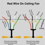
Identifying the Wires
Ceiling fan wiring typically consists of three wires: black (hot), white (neutral), and green or bare copper (ground). The black wire carries electricity from the power source to the fan, while the white wire completes the circuit by returning the current to the power source. The green or bare copper wire provides a safety path for excess electricity, protecting against electrical shock.
Additionally, there may be other wires for controlling fan speed, light, or remote operation. These wires typically have different colors or markings to distinguish their function.
Terminal Connections
Ceiling fans have a terminal box that houses the electrical connections. Inside the terminal box, you will find several terminals: black (L), white (N), and green (G). The black and white terminals are for connecting the black and white wires from the power source, respectively. The green terminal is for connecting the green or bare copper ground wire.
Wiring Procedure
To connect the wires, follow these steps:
- Turn off the power at the main electrical panel.
- Remove the ceiling fan canopy and locate the terminal box.
- Strip the insulation from the ends of the wires, exposing about 1/2 inch of bare wire.
- Wrap the bare wire of the black wire clockwise around the black terminal and tighten the screw.
- Wrap the bare wire of the white wire clockwise around the white terminal and tighten the screw.
- Wrap the bare wire of the green or bare copper wire clockwise around the green terminal and tighten the screw.
- Secure the wires in place using the wire nuts provided with the fan.
- Reconnect the ceiling fan canopy and turn on the power at the electrical panel.
Speed and Light Wiring
Ceiling fans with multiple speed settings or lights require additional wiring connections. These connections typically use colored wires corresponding to the specific function. For example, blue for high speed, yellow for medium speed, and red for low speed. The manufacturer's instructions should provide a detailed wiring diagram for these additional connections.
Remote Control Wiring
Ceiling fans with remote control capabilities require a receiver to be installed in the fan's housing. The receiver then connects to the fan's wiring, allowing the remote to control the fan's speed, light, and other functions. The wiring for the remote receiver typically uses separate wires and terminals for each function, as indicated in the manufacturer's instructions.
Safety Precautions
When working with electrical wiring, always prioritize safety. Wear appropriate safety gear, such as gloves and safety glasses. Ensure the power is turned off at the main electrical panel before starting any work. If you are not confident in performing electrical work, seek the assistance of a qualified electrician.

Ceiling Fan Wiring Diagram With Capacitor Regulator

Wiring A Ceiling Fan And Light With Diagrams Ptr

How To Wire A Ceiling Fan Control Using Dimmer Switch

How To Wire Ceiling Fan Wiring Diagram Connection

Wazipoint Engineering Science Technology Celling Fan Wiring Diagram With Capacitor Connection

How To Replace A Capacitor In Ceiling Fan 3 Ways

Ceiling Fan Wiring Diagram

Ceiling Fan Capacitor Wiring Diagram Mb Electrical

Brahma Prakash On Linkedin Wiring Diagram Of A Ceiling Fan

Ceiling Fan Wiring Diagram With Capacitor Connection Circuitstune